Dit item is niet op voorraad
Bekijk deze advertentie in het archief


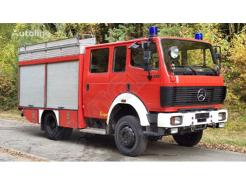
Mercedes-Benz 817 MERCEDES FIRETRUCK
19 750EUR
Prijs excl. BTW
- ≈ 21 202 USD


MAN 12.232 Firetruck 4x4
32 000EUR
Prijs excl. BTW
- ≈ 34 353 USD


MAN TGM 18.280 4x4 Firetruck
121 000EUR
Prijs excl. BTW
- ≈ 129 898 USD


MAN 4x4 Firetruck Feuerwehr DOKA Expedition Camper
45 800EUR
Prijs excl. BTW
- ≈ 49 168 USD


MAN 4x4 Firetruck Feuerwehr DOKA Expedition Camper
48 800EUR
- ≈ 52 388 USD


MAN LE 18.220 4x4 FIRETRUCK FEURWEHR
55 000EUR
Prijs excl. BTW
- ≈ 59 044 USD


Mercedes-Benz 2038 4x4
76 400EUR
Prijs excl. BTW
- ≈ 82 018 USD


Mercedes-Benz 1017 AF 4X4
12 500EUR
Prijs excl. BTW
- ≈ 13 419 USD


Mercedes-Benz 1019 AF 4X4
12 500EUR
Prijs excl. BTW
- ≈ 13 419 USD


Iveco 135-17 Manual + Firetruck
14 950EUR
Prijs excl. BTW
- ≈ 16 049 USD
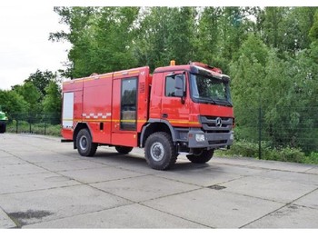
Nieuw Brandweerwagen Mercedes-Benz 2031 4x4 Firetruck
Gepubliceerd: 4jr. 10mnd.


Gepubliceerd: 4jr. 10mnd.
prijs: Price on request
Model / Type: 2031 4x4 Firetruck
Construction: Firetruck
Suspension: Leaf spring suspension
Water tank 6000 ltr GRP
Foam tank 500ltr GRP
80 meter hoses highpressure with jet/ spray nozzle
Pump 3000l/m at 10 bar and 250 l/m at 40 bar
Monitor WG 2400VM model 330 deegrees horizontal angle rotations
Body structure aluminium / GRP
Six equipment lockers
One rear locker for pump operations
Rear ladder
Electronic siren P/A system complete with 1*100 watt speakers
Two emergency warning flashing lights mounted at the rear
one on each side
Cab spot light mounted one on each side of the front wind shield posts
Telescopic masts with LED Lighting
Construction and Design
Body is made of aluminum material interconnected with bolts and screws
without welding. Neither steel material nor any type of
welding or bonding is used on the body. The complete external paneling of the rear body is made from aluminum sheet fitted to the
structural members
The superstructure is modular type. Complete body including Water and foam tank are mounted on a heavy duty ladder type sub frame
This sub frame is connected with the mainframe of the chassis with heavy duty rubber / steel shock absorbers. In such a way all torsion
– stress transmitted to the chassis during off-road drive and cornering
are reduced to minimum
granting excellent stability
The body is designed in such a way to allow maximum accessibility to all areas to be served and inspected. Provision is made for all
major vehicle components to be removed in an easy manner
Roof Deck
The top of the superstructure will be decked in chequered aluminum plates suitably strengthened and designed to bear the weight of 4
fire men without distortion or damage
Suitable brackets for 1 (one) extendable ladder are installed on the top of the vehicle. The extension ladder consists of 2 sections. Fully
extended length of the ladder is min. 8.5 m and closed length is 4.9 m. There is sliding beam gantry system for easy access to sliding
ladder which is placed on the top of the vehicle. By using this system
the extension ladder will be rolled in/out without climbing the
roof. While driving
the ladder handle is placed to the rear body of the vehicle by using handle locking device and the ladder is stored on
the roof
On the roof
there is a closed aluminum box for 4 (four) nos of 3 m suction hoses. The decking will be bordered by allow safety railing
with lighting system for side of the vehicle
In the rear right hand side of the body
there is one permanent heavy-duty light alloy ladder installed which allows getting onto the top
of the roof. The ladder is swivel type with two sections. Lower section is folded up and locked during driving with a special locking
device located on the left hand side. Ladder rugs are built in cylindrical shaped sections with antislip surface. Handgrips are provided
where necessary
There are four (4) storage lockers in total
two located on each side of the vehicle. Storage lockers are closed dust and waterproof by
light alloy spring type rolling shutters. The floor of the storage locker will be covered with aluminium plates. Drain holes are provided on
the floor of the lockers to prevent accumulation of water
The lockers can be opened when a part of the equipment blockades them
which is guaranteed thanks to the dual skinned design. Roller
shutters offer smooth running and low noise employment. They are equipped with full width bar-lock. Proper equipment mounting
brackets
swing-out shelves
slide-out trays
slings etc. inside the lockers are provided
so that the equipment and accessories are well
secured and kept inside the lockers during driving and cornering of the vehicle and a fast and safe removal of the stored equipment will
be possible. Racks inside the storage lockers are made of height adjustable aluminium profiles
The interior for the hose lockers will be smooth and free from all projections such as nuts
sharp angles orbrackets which may damage
the hose. The hoses are stored inside the hose box sections. The material of this box is made of corrosion resistant aliminum
Inside every storage locker
there are LED lights mounted which are actuated by opening of the stowage lockers. The storage lockers are
identified with numbers (1
2
3
4
….. )
The pump compartment is located at the rear of the vehicle
closed by an aluminium roller shutter. Drain holes are provided on the
floor of the pump compartment to prevent accumulation of water. Inside the pump compartment
there are LED lights mounted which
will be actuated by opening the pump compartment. The roller shutter of the pump compartment offer smooth running and low noise
employment. It is equipped with full width bar-lock
Foot boards with non-slip surface are installed under the storage lockers where needed to access to higher level storage lockers. They
will be design to withstand the weight of 2 fire fighters. During driving
they can be folded up and for operation it can be folded down
and will be covered by chequered aluminum. In other words
they serve as the doors of the lower storage lockers during driving
Water tank has a usable capacity of 6.000 liters. The tank will be constructed throughout including baffles in stainless-steel material
Material certificate will be supplied at the time of commissioning. Tank is made GRP material with min. 10 mm thickness
Baffles will be installed inside the tank. Access through these baffles is provided for maintenance. The design provides long service life
Water tank is connected to sub frame by dual spring connector at each side
Water Tank Fittings
• • Min. 450 mm dia. Manhole filler is fitted with hinged closing cap and located on top of the tank providing access for
inspection and routine maintenance
• • Tank drain with manually actuated ball valve is provided
• • Overflow system is provided to avoid over and under pressurization in the tank
• • The tank is fitted with VLI 2.0 electronic dial type contents gauge to indicate liquid level in the tank
• • There will be two hydrant filler inlets
each with a 2 1/2" male BS type coupling and female blank cap
located at low level at
the rear of the appliance below the pump bay (enabling hydrant supply to be connected whilst the pump bay door is closed)
one each
on the left and right sides
and provided with a change-over valve to select between hydrant-to- pump and hydrant-to-tank
4) FOAM TANK
Foam compound tank has a usable capacity of 500 liters. Tank material is GRP material with min. 10 mm. thickness
The tank is constructed throughout including baffles with GRP plates. The foam compound tank is incorporated to the water tank
Foam Compound Tank Fittings
• • An expansion dome is incorporated into the top of the. A cover is be provided for inspection or top filling
• • Overflow system is provided to avoid over and under pressurization in the tank
• • The tank is fitted with VLI 2.0 electronic dial type contents gauge to indicate liquid level in the tank
• • Tank drain with ball valve is provided in suitable position in the bottom of the tank to facilitate complete removal of
accumulated sediment
• • There is a suction line to the foam proportioning system with ball type valve
• • There is a tank filler inlet with 2,5" male BS coupling and female blank coupling and provided with a ball type valve
Fire pump VFPN-H 300 is a centrifugal water pump that generates 3000 l/m at 10 bar and 250 l/m at 40 bar. In other words
the pump is
suitable for normal & high pressure operations. The pump is located in the rear of the truck in a pump compartment
Pump body
normal pressure impeller will be made of hard anodized aluminum material and high-strength stainless steel pump shaft
Sealing of the pump is mechanical sealing. High pressure impeller will be made of bronze material
Pump gear is made of crom-nikel. The pump is driven by the power take off of the chassis with P.T.O and a pump mounted gearbox
Pump is equipped with an automatic piston priming system that consists of 2 priming pistons. A manual override switch is also available
Piston priming system is driven via V- belt. The control is electric and automatic
by pressure in the fire pump. Suction lift is approx. 3m
within 30 sec. (in compliance with EN 1028) with lift of up to 8m. Automatic thermal protection is provided for the pump
Connections
• • 1 suction inlet 4†with Instantaneous coupling
filter and blind cap with butterfly type valve
suitable for connection of
suction hoses
• • 4 (four) normal pressure outlets 2 ½†with 2 ½†BS type coupling
blind cap and ball valve located at the rear of the body. 2
(two) will be located on the left hand side and 2 (two) will be located on the right hand side of the pump
• • There is a high pressure outlet with ball type valve connected to the high pressure hose reel
• • 1 (one) pump to tank fill line c/w quarter turn ball valve is provided
• • 1 (one) outlet for monitor operation is provided
• • There will be a suction line to the water tank
with butterfly valve
Piping
The water pipe lines and the foam concentrate pipe work are made of highly corrosion resistant material. The piping system design
keeps the pump area free from irritating delivery hoses
and allows selective feeding of the tank or the pump
Pump Control Panel
Pump control panel is located in the pump compartment
mounted on the pump
A metallic identification plate is permanently installed on the pump operator’s control panel. It identifies the fire pump serial number
model
and performance characteristics
• Pump Connection (For PTO engagement)
• Engine Start/Stop
• Monitor Button (Monitor Valve On/Off)
• Automatic Suction
• Left Side Illumination
• Right Side Illumination
• Rear Sportlight
• Throttle Up/Down
• Idling
• Pressure Gauge
The following manual gauges are located on the pump
• • Normal pressure gauge according to EN 837-3 norms
• • High pressure gauge according to EN 837-3 norms
• • Water inlet pressure according to DIN 14 421 norms
Front Display On driver’s Cabin
• • Indication of open doors/lockers
6) FOAM PROPORTION SYSTEM
manual "around the pump" foam proportioning system is provided. This system operates on principle of measuring pump and foam
concentrate flow rate and adjusts the foam mixing device to desired foam flow rate according selected proportioning rates between 0%
3% and 6%
The foam/water solution is discharged from all outlets of the vehicle. Foam system is also capable of using foam from external source if
required. Suction capacity of external foam suction is 2 meters. The system is corrosion resistant gunmetal and 316L grade stainless
steel
WG 2400 VM model manual operated monitor will be mounted on the working deck .The discharge rate is 2400 lpm at 10 bar. Max
working pressure of the monitor is 16 bar
The horizontal rotation angle of the monitor is 330°. The elevation angle range of the monitor is - 10° to +700. Throw range is 60 m
water and 50 m foam. The monitor is equipped with an adjustable jet / spray water nozzle and foam barrel
suitable for all foams
with
resistant hard anodized light alloy aluminium